icon.
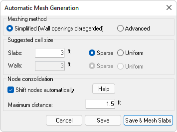
icon.The program will automatically generate the floor mesh for you using the ADAPT-Mesher. The inputs for automatic mesh generation are accessed through the Automatic Mesh Generation dialog window. Refer to the Tips for Meshing topic for information on modeling tips to ensure the program can converge to a mesh.
To access the automatic mesh generation dialog:
Go to Analysis>Meshing and click the Mesh Generation icon.
Automatic Mesh Generation Options
| Option | Description |
|---|---|
|
Meshing Method |
|
|
Simplified (Wall openings disregarded): |
Selecting this option, the program ignores openings modeled within walls. This option can be used with most models. If your model includes wall openings you must use the Advanced option.
|
|
Advanced: |
The Advanced option should be used in models that contain wall openings. Selecting this option unlocks the options for specifying the Suggested Cell Size options for walls.
|
| Suggested Cell Size | |
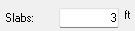
| Slabs |
Input for the suggested cell size for meshing the slab. A value of 3 feet (1 meter) is the default value and can be used to mesh most models. Increase this number to produce a coarse mesh, decrease this number to achieve a finer mesh.
Note: In most cases, six to eight divisions for the typical span of a floor system gives design values (moments, shears) that are within two percent of the value obtained if a very fine mesh is used. This accuracy applies to design stresses too. In your first attempt, start with a suggested cell size of three feet (1.00 meters). Most structural models can be analyzed and designed well with 3,000 to 4,000 cells. A complex structure may require up to 6,000 cells. It is very rare that you need to solve a single level structure needing more than 10,000 cells. If you do, chances are that the structural modeling is not efficient.
Note: The Technical Note TN184_FEM Mesh Density and Accuracy of Design Values.pdf gives a detailed evaluation of the mesh density and the accuracy of the solution.
|
| Slabs>Sparse/Uniform |
Sparse:
When Sparse is selected, the program will grow and decrease the spacing of cells depending on the number of nodes in a location. The mesh will get dense at locations with multiple nodes and sparse in areas with no nodes.
Click image to enlarge Uniform:
When Uniform is selected, the program will space the mesh cells uniformly throughout the slabs.
Click image to enlarge |
| Walls |
Input for the suggested cell size for vertical meshing of the walls. In most cases the value should correlate with the value for slabs. Increase this number to produce a coarser wall mesh, or decrease this number to achieve a finer wall mesh.
|
| Walls>Sparse/Uniform |
Sparse:
When Sparse is selected, the program will grow and decrease the spacing of cells depending on the number of nodes in a location. The mesh will get dense at locations with multiple nodes and sparse in areas with no nodes. Uniform:
When Uniform is selected, the program will space the mesh cells uniformly throughout the walls. |
| Node Consolidation | |
| Shift Nodes Automatically |
When this option is checked, the program will shift the analysis nodes of the model in locations where multiple nodes are in close proximity to try and consolidate nodes in a location. Refer to Node Shifting topic for more information.
|
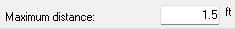
| Maximum distance |
Sets the maximum distance that the program will shift analytical nodes.
Note: For the node consolidation input, select a value no more than 4 times the average slab thickness in the model. A distance between two to four times the average slab thickness gives reasonable results.
|
To Generate an Automatic Mesh:
Go to Analysis>Meshing panel and click on the Mesh Generation  icon.
icon.
Set the settings in the Automatic Mesh Generation dialog window that you want to use for the meshing of the slab (and walls if applicable). The default values are recommended for most models.
Click the Save & Mesh Slabs button.
The image below shows an example of a structural model ready for mesh.
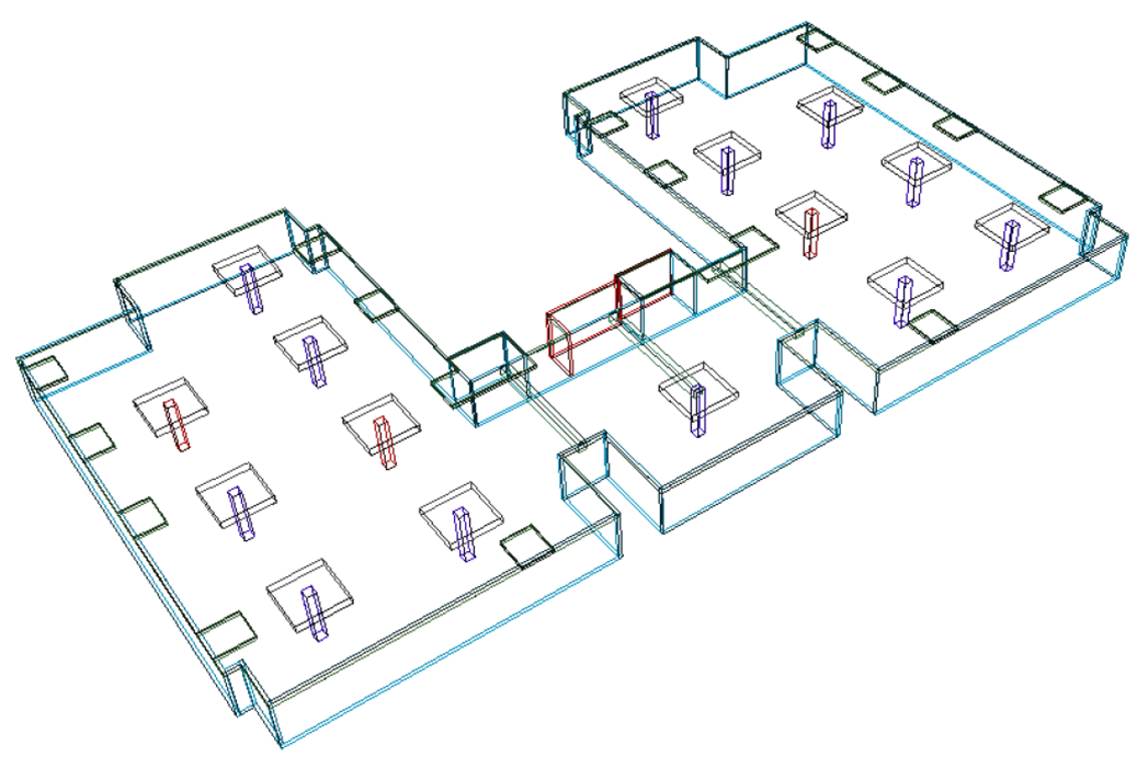
Click image to enlarge
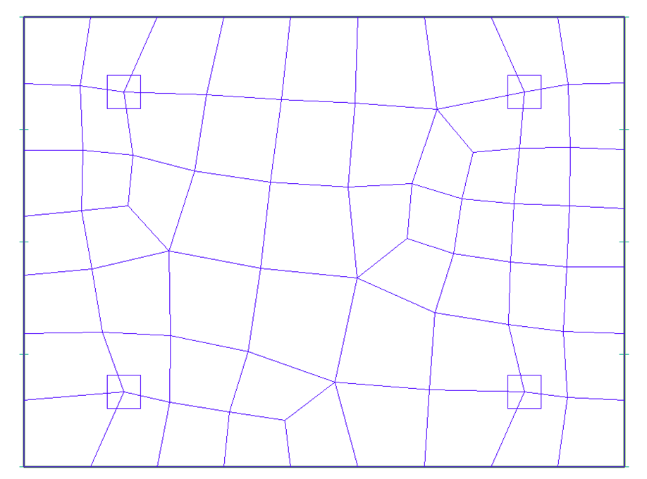
Once successful, the program will display the mesh, as is shown in the following image.
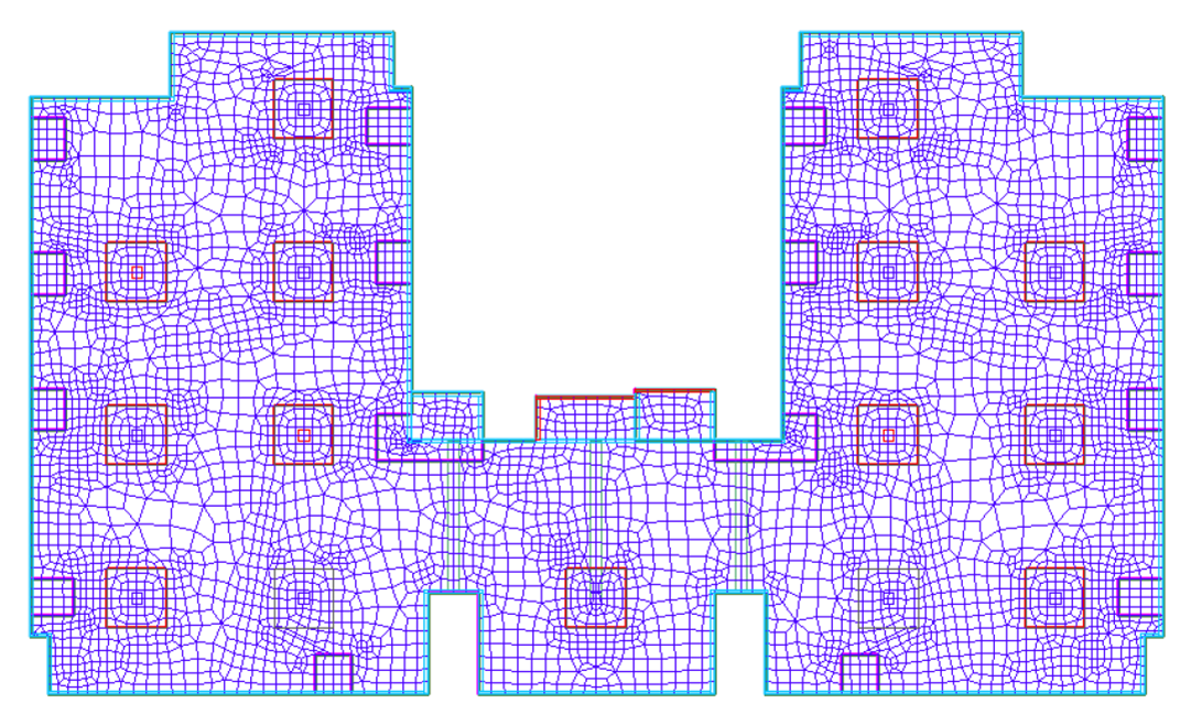
Click image to enlarge
If the program fails to converge to a mesh, the program will return an error message and display the Component Representatives on screen. Please refer to the Component Representatives topic for more information on the use of component representatives to diagnose mesh errors.